
Wherever you have an electrical current you will have an electromagnetic field generated. Nowadays power lines are found everywhere above and below ground as well as throughout most buildings. That means there will be a ubiquitous electromagnetic field with a dominant frequency of the mains power line.
A spectrum analyser is a device that can be used to see what signals are present and at what frequencies. That is, in addition to the mains what other signals are also travelling on the power lines.
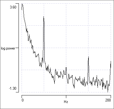
Fig. 1 below shows a power spectrum of the 50 Hz mains electricity on a spectrum analyser (from St Andrews in the UK). As expected the mains 50 Hz single is strongest but other small signals are also present. They are harmonics of the 50 Hz mains.
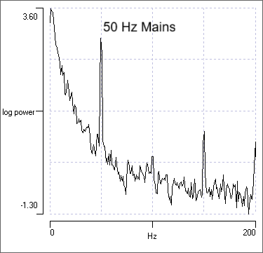
These peaks in the power spectrum represent pure sine wave signals but they can have noise components around them which makes them “dirty”. The questions I am looking to answer here are what is the cause of the electrical noise on the mains and what problems does that “dirty” electricity create. I’ll try to keep this as non-technical as possible.
But before getting to that I look at the development of electrical power generators and the different types of electricity.
Development of Electricity Generation
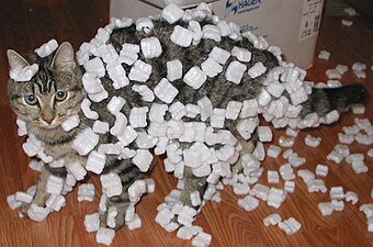
The history of electricity generation spans centuries, beginning with early observations of static electricity. In the 6th century BC, Greek philosopher Thales of Miletus noted that rubbing amber could attract light objects, an early demonstration of the triboelectric effect. That results from a transfer of charge between two objects. Static charges are built up on dry surfaces like with the cat in Fig. 2 below.
Lightning is an example a static charge equalising or going to ground as pictured in the top image above. Static charge is built up on the end of the post until the pressure or voltage difference to ground is so large that the electrons at the tip discharge to ground.
Systematic experimentation began after the scientific revolution, with significant milestones including the invention of the voltaic pile by Alessandro Volta in 1800, the first device capable of producing a continuous electric current. That was a DC meaning direct current. This breakthrough enabled further research into electricity and magnetism.
The foundational principles of electricity generation were established in the 1830s by British scientist and biblical creationist Michael Faraday, who discovered electromagnetic induction — the process of generating electric current by moving a magnet within a coil of wire. This discovery led to the development of the first electric generator, the Faraday disk, and laid the groundwork for modern power production. Faraday’s work also contributed to the invention of the electric motor.
The first practical application of electricity generation occurred in 1882 when Thomas Edison opened the Pearl Street Station in New York City, a central power plant that used steam engines to drive dynamos and supplied direct current (DC) to power public lighting.
Around the same time, the development of alternating current (AC) systems by Nikola Tesla and George Westinghouse revolutionized power transmission. AC permitted electricity to be transmitted over long distances efficiently, overcoming the limitations of DC.
Through a series of discoveries, the DC generating dynamo was replaced by the AC alternator, which was capable of generating alternating current (AC). Large two-phase alternating current generators were built by a British electrician, J.E.H. Gordon, in 1882. The first public demonstration of an AC system was given by William Stanley Jr., an employee of Westinghouse Electric in 1886.
The Niagara Falls hydroelectric power plant, completed in 1895, was a landmark project that demonstrated the feasibility of long-distance AC transmission, carrying power 40 kilometers to Buffalo.
The 20th century saw the expansion of large-scale power generation using various energy sources. Coal became the dominant fuel in many countries, including the United States, where it accounted for over half of electricity production by the 1960s.
Energy released from thermal coal produced superheated steam that turned a turbine with a rotating shaft and an attached alternator produced an AC current that converts mechanical energy to electrical energy for use in an external circuit.
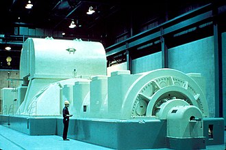
In most generators, which are rotating machines, a source of kinetic power rotates the generator’s shaft. The sources of mechanical energy used to drive generators nowadays include steam turbines (Fig. 3), gas turbines, water turbines, internal combustion engines, wind turbines and even hand cranks.
Hydroelectric (water) power also grew significantly, with major projects like the Hoover Dam (completed in 1936) and the Snowy Mountains Hydro Scheme (completed in 1974) in Australia. The development of steam turbines, such as the one invented by Sir Charles Parsons in 1884, further improved the efficiency of thermal power plants.
In Australia, electricity generation began in the 1880s, with the first public demonstration of electric lighting in Brisbane in 1882 and the installation of electric street lights in Sydney by 1885. The first hydroelectric plant in Australia was established in Thargomindah in 1898, using water pressure from a bore.
Over time, state-based electricity grids developed, culminating in the creation of the national and state electricity grids in most developed countries. Though a small area grid in Sydney initially used DC it was abandoned for AC, which allowed much wider coverage.
The 21st century has seen a shift toward what are claimed to be renewable energy sources. The use of solar photovoltaics and wind power has expanded rapidly, particularly in the Western world, driven by the alleged need to reduce greenhouse gas emissions, that is, carbon dioxide and to combat so-called ‘climate change’. I have written a lot about those claims on this site.
DC or AC Electricity?
Already we have introduced DC and AC electricity, but what is it?
Contrary to popular beliefs electricity is not the transmission of electrons through wires. Electrons are involved but electricity is the energy transmitted through a conducting material. The electrons in the conductor provide a medium for that energy to flow.
In DC the electrons do move or drift through the wire conductor and their flow depends on the material used. But the energy in or on the conductor travels at the speed of light in the material, which is of order 50% of the speed of light in a vacuum. That speed depends on the particular material properties of the conductor used.
Copper with its high conductivity, and low price, is extensively used in electronics and electric wiring. Silver and gold have high conductivity and are used on circuit boards even though they are more expensive.
The inverse of conductivity is resistivity. Only when a conductor becomes superconducting does the resistance in the conductor go to zero and the energy is transmitted without loss.
The same is true for an AC system except the electrons do not drift from one electrode to another. (For historical reasons charge carriers drift from positive to negative).
Under AC excitation, when a AC generating alternator is connected to the circuit, the electrons in the conductor, a crystalline metal lattice, oscillate around their localised positions in that lattice. You can consider this to be an electron gas close to the surface of the metal oscillating under an applied electromagnetic field. The penetration depth of the electric field into the metal is small.
The conductivity of a conductor depends on the line frequency. At DC the energy losses are much higher than at typical AC frequencies of 50 Hz or 60 Hz. Therefore it makes sense to use AC power to transmit it over long distances.
Also it makes sense to transform the AC voltage to transmit power over long distances. That means high pressure is applied on high-tension transmission lines but transformed down to 110 V or 240 V at the local area where it is used.
High-tension power lines operate at voltages typically ranging from 69 kV to over 765 kV to minimize energy loss during long-distance transmission. In practice, transmission lines often carry voltages such as 115 kV, 138 kV, 230 kV, 345 kV, 500 kV, and even up to 765 kV in some systems.
Transformers are required to up or down convert voltages. An AC transformer is a device that transfers energy between two or more circuits through electromagnetic induction, which relies on an AC current.
While transformers are inherently designed for AC operation, they can also function with changing currents from DC sources if the input current is interrupted or switched, as seen in ignition coils and flyback transformers, where a sudden change in current induces a high voltage spike.
However, continuous AC is the standard for stable and efficient transformer operation. The output of a transformer is typically AC, and devices requiring DC must use an additional rectification circuit.
Synchronous Generators
Synchronous Generators are electricity generators that have an alternator generating an AC output. Synchronous machines are directly connected to the power grid and need to be properly synchronized during startup. As you might imagine any instability in the rotation of the turbine shaft will translate into an instability in the supplied AC current. Also since multiple generators are connected directly to the grid they require special control to enhance the stability of the power system.
Depending on where you live the mains AC power is usually rated at 50 Hz or 60 Hz. Historically it was not so uniform and many different frequencies were used in different regions. The mains frequency is merely determined by the rotation speed of the turbines that generate the power. 60 Hz means 60 cycles/second or 60 full rotations of the shaft every second. That is 3,600 rpm, revolutions per minute, for a two-pole generator. 50 Hz therefore means 3,000 rpm.
Control systems at the generator stations control the number of revolutions per minute, but all generators on the interconnected grid must be controlled to the same frequency. When they are not we get random power fluctuations and fluctuations in the AC frequency deviating from the pure sine wave at either 50 Hz or 60 Hz.
A slight deviation outside the range of 49.5 Hz to 50.5 Hz in the case of 50 Hz mains can cause problems such as flickering lights, malfunctioning medical equipment, and industrial machinery shutting down. The narrow tolerance is critical because stable frequency is the backbone of reliable power, and even small fluctuations can disrupt sensitive devices and systems. The frequency is maintained by governors that adjust engine speed in response to load changes, ensuring the output remains within this tight range.
Small deviations result in a host of other frequencies generated near the required mains frequency. See Fig. 4. This is called “dirty electricity”, however more often than not the term is used for electricity generated by coal or hydrocarbon based fuels, which are incorrectly called fossil fuels. Here I use the term for when the power line frequency at a local site is not a pure sine wave.
The precise control of the power line frequency is a significant problem when large numbers of rooftop photovoltaic cells (solar panels) and large arrays of solar farms are connected to the grid. They do not have a rotating shaft that is synchronised. Therefore a local real time clock is used to artificially generate an AC power signal at the mains frequency of that country or area.
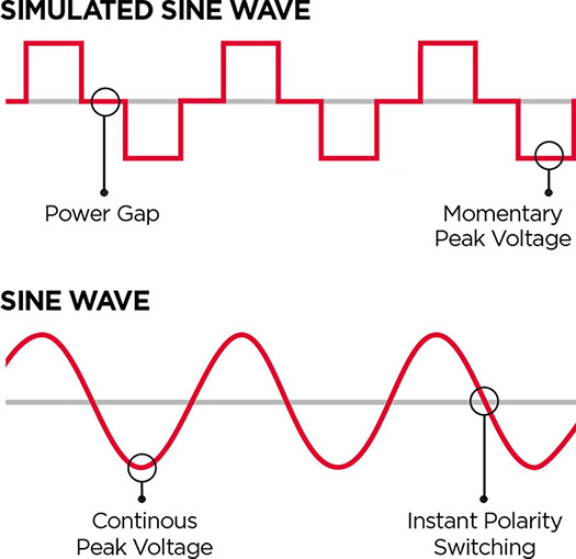
The AC power signal digitally synthesized in an inverter and that digitisation will add higher frequency components. The simulated sine wave in Fig. 5 can be considered to be the sum of desired pure sine wave plus many harmonics of that pure sine wave. And any mismatch from the mains frequency will produce offset signals which manifest as harmonics with the mains frequency.
An important problem with solar generation potentially can occur when the solar power generation becomes a significant proportion of the entire grid. The frequency of all solar generators must be tightly controlled by reference to real time clocks. But also the total power from solar varies drastically between day and night. When solar power is low, especially morning and evening at peak consumption, the base load turbines must compensate and that means an increased load on their rotation speed, which must be controlled to maintain the mains frequency in the tight range required.
Wind power generators are another problem. They do have a rotating shaft and many are connected in an array. The wind moves the blades that turns the rotor through a gear box that increases the rotation per minute of a shaft which is then connected to an alternator that produces electrical power. A series of gears increase the effective rotor rotation speed of the blades from about 13 rpm to 20 rpm to what would be the equivalent to 1500 rpm to 1800 rpm for the shaft. This equivalent shaft speed of 1500 rpm to 1800 rpm is the speed required to generate AC power for the grid at the desired frequency with a 4-pole generator.
All deviations from a pure sine wave frequency introduce disturbances in the mains electricity delivered to homes and other buildings. That means you get a noisy or dirty sine wave signal on your mains power supply.
Electricity Meters
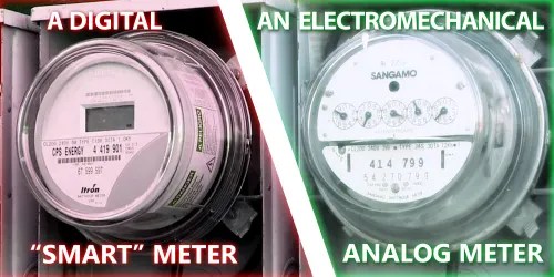
There are two types of electricity meters: analog and digital. Some typical devices are shown in Fig. 6.
Analog meters are those that have been used for the last 100 years. As shown in Fig. 6 on the right, the amount of power consumed is displayed by a set of small analog meters.
Digital meters like the one in Fig. 6 on the left are now becoming the standard. They convert the analog mains signal frequency to a digital representation like the simulated sine wave in Fig. 5.
A digital meter uses digital electronics and can also be a “smart” meter, which means it has a built-in communications module, like a cell phone, to communicate with a base station and avoid the need for a human to visit your home to read the meter.
Electronic meters display the energy used on an LCD or LED display, and some can also transmit readings to remote places. In addition to measuring energy used, some electronic meters can also record other parameters of the load and supply such as instantaneous and maximum rate of usage demands, voltages, power factor and reactive power used etc. They can also support time-of-day billing, for example, recording the amount of energy used during on-peak and off-peak hours.
The meter has a power supply, a metering engine, a processing and communication engine (i.e. a microcontroller), and other add-on modules such as a real time clock (RTC), a liquid crystal display, infra red communication ports/modules and so on.
The metering engine is given the voltage and current inputs and has a voltage reference, samplers and quantisers followed by an analog to digital conversion section [A to D convertor] to yield the digitised equivalents of all the inputs. These inputs are then processed using a digital signal processor to calculate the various metering parameters.
The processing and communication section has the responsibility of calculating the various derived quantities from the digital values generated by the metering engine. This also has the responsibility of communication using various protocols and interface with other addon modules connected as slaves to it. Wikipedia
Just because you have a “smart” meter attached to you house does not mean it is communicating with a base station. It could be, but it needs the communication module to do so. It will be a digital device and thus it will generate some level of digitisation noise.
Just because you have a “smart” meter does not mean a high level of electrical noise pollution necessarily. It depends on the sources of noise on the line delivering mains power to the premises, in addition to the electrical noise generated by modern household lighting (LEDs) and appliances (see below).
The mains power will still be coming directly from the grid and bringing with it all of the noise it has accumulated from the grid. Therefore in my opinion the two main sources of dirty electricity are:
- Higher frequency voltage signals and spikes on the power supply side introduced to the mains through, for example, solar panel generators with digital inverters, and other digital electronics;
- High-frequency voltage transients and harmonics coming from lighting, digital devices and appliances inside buildings, where the building wiring acts as an antenna to pick up the noise.
These noise sources are transmitted along the power lines and wiring in buildings. They are the ubiquitous electrical noise in a modern city.
High frequency components can be filtered out but not harmonics or noise near the mains frequency (50 Hz or 60 Hz). That is called low frequency noise and is extremely difficult to suppress.
High frequency means up at radio frequencies (RF). Frequencies of 30 kHz up to 300 GHz are considered RF, though above 3 GHz we call microwave. Home Wi-Fi is a significant source of microwave radiation in the home. The low end of RF frequencies are used by radio and TV stations and therefore dirty electricity can affect the reception of those signals.
Having a good technical ground for your home’s power supply is important to reduce electrical noise affecting RF signal reception. The ground line of your power circuits should be connected to a metal water pipe or a dedicated metal conductor that goes deep into the ground. A qualified electrician is needed to do this.
Is using only solar power cleaner? Yes, if you are generating your own AC power from an inverter which synthesizes a near pure sine wave. With the inverter powered by a DC current from the batteries connected to your solar rooftop panels, you would only have the digitising noise of the synthesised power signal from your inverter at the mains frequency.
That is, if you have completely disconnected your house from the AC mains power grid, but not if your solar power system is tied into the grid (which most are). Then some of the outside noise will still come into your system.
Even so if you use a switched power supply like in a computer, or digital TVs, or LED lights or lights using a transformer, or other electronics, the wires in your walls act as an antenna to pick up the noisy electrical energy from those noisy household devices.
Dirty Electricity
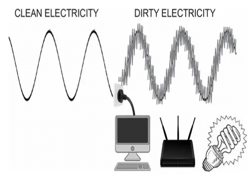
Dirty electricity refers to high-frequency voltage transients and harmonics that disrupt the standard 50 Hz or 60 Hz AC electrical current flowing through the wiring in a building. It is often characterized by erratic microsurges and spikes of energy, often described as electrical “trash,” that travel along power lines and building wiring.
For the technically minded the short video below shows a power spectrum of the electrical signal which may be present. This gives you an idea of the noise present on the power line circuits.
The frequency range of dirty electricity typically spans 100 Hz to 100 MHz (megahertz), encompassing mid-to-high frequency electrical noise. The higher frequency disturbances are generated by electronic devices that manipulate the standard electrical current, such as switched-mode power supplies, compact fluorescent lights, dimmer switches, solar inverters, and other energy-efficient appliances.
All energy in the power circuits radiate an electromagnetic field (EMF). This includes the mains frequency and its harmonics (Fig. 1). The higher-frequency components in dirty electricity also radiate an EMF into living and work environments, potentially contributing to electromagnetic interference (EMI). See Fig. 7.
Dirty electricity can interfere with the proper functioning of appliances and electronic equipment, a phenomenon known as electromagnetic interference or power line EMI. Today, when an electrical device draws power from a building’s wiring, its not only getting the standard AC electricity it needs as initial input, but also the erratic spikes and surges of energy (i.e., the dirty electricity) also present on the wiring. This can be problematic for electrical devices that are not well equipped to deal with this dirty electricity.
It also appears that dirty electricity may disrupt important electrical processes within our bodies, the most sensitive “electrical equipment” we have. Exposure to this type of electro-pollution has been associated with a wide variety of health problems such as cancer, asthma, sleep disturbances, fatigue, skin rashes and tingling sensations, allergy symptoms, headaches, muscle and joint pain, brain fog, memory loss, ADD/ADHD symptoms, depression, and more.
I am no expert on the health issues of dirty electricity but I am sure that more research in that field needs to be done. However the following is excerpted from a research paper which looked for health improvement when dirty electricity was filtered / reduced in the environment. (The full paper is available as a pdf from the author.)
Dirty electricity is a ubiquitous pollutant. It flows along wires and radiates from them and involves both extremely low frequency electromagnetic fields and radio frequency radiation.
Until recently, dirty electricity has been largely ignored by the scientific community. Recent inventions of metering and filter equipment provide scientists with the tools to measure and reduce dirty electricity on electrical wires. Several case studies and anecdotal reports are presented.
Graham/Stetzer (GS) filters have been installed in schools with sick building syndrome and both staff and students reported improved health and more energy. The number of students needing inhalers for asthma was reduced in one school and student behavior associated with ADD/ADHD improved in another school.
Blood sugar levels for some diabetics respond to the amount of dirty electricity in their environment. Type 1 diabetics require less insulin and Type 2 diabetics have lower blood sugar levels in an electromagnetically clean environment.
Individuals diagnosed with multiple sclerosis have better balance and fewer tremors. Those requiring a cane walked unassisted within a few days to weeks after GS filters were installed in their home. Several disorders, including asthma, ADD/ADHD, diabetes, multiple sclerosis, chronic fatigue, fibromyalgia, are increasing at an alarming rate, as is electromagnetic pollution in the form of dirty electricity, ground current, and radio frequency radiation from wireless devices.
The connection between electromagnetic pollution and these disorders needs to be investigated and the percentage of people sensitive to this form of energy needs to be determined.
Electrification of cities and towns has lifted billions out of poverty. So we cannot say that that has been a bad thing. The sources providentially provided by the Creator to generate the electricity should be seen as a blessing.
The ongoing insane push to “go green” and leave the hydrocarbons (coal, petroleum, gas etc) in the ground to allegedly stop the planet warming is a great concern. If fully implemented it would turn off the electricity and lights in most countries, especially the developing world.
Having said that we should look carefully at the impact of modern digital devices in regards to the electromagnetic pollution they add to the environment. Innovation can mitigate against that if it is properly addressed. So let’s not “throw the baby out with the bath water”!
But let separate fact from fiction. Modern digital technology is not itself inherently evil. It is how it is used that counts. The evil is in the heart of man. The billionaire oligarchs cannot be trusted to not use everything at their disposal to enslave the masses in order that they may achieve their own goals. Global surveillance and the digital prison is far more serious and concerning than having a “smart” meter attached to your home.
Related Reading
- COVID-19 and 5G
- Global Surveillance | Separating Fact from Fiction
- How the Oligarchs Planned to Enslave the World
- What’s Your Carbon Footprint?
- Building the Digital Prison
- Coal, the Creator’s Providential Provision
- It Was No Accident: All Forms of Energy Were Provided by the Creator
- The Truth Behind Cheap Green Energy
- The Problem with All Green Energy is …. Basic Physics
Free Subscribers
Subscribe to our Newsletters as a Free Subscriber and be notified by email. Just put your email address in the box at the bottom of your screen.
You’ll get an email each time we publish a new article. It is quick and easy to do and totally free. You only need do it once.
Premium Subscribers
Subscribe to our Newsletters as a Premium Subscribers at $5 USD/month or $30 USD/year (you choose).
Paid Premium Subscribers will get exclusive access to certain content I publish. That will only cost you a cup of coffee per month.
Also you’ll be able to download, for free, a PDF of my book Apocalypse Now and also a PDF of my book Physics of Creation The Creator’s Ultimate Design for Earth.
You can download them from the link below.
This is how you can support my work. I have been publishing this website for 10 years now and up to 2024 I never asked for any support.
Press the button “Premium” on the front page to find a list of Premium content. Thanks so much to all supporters.
At a minimum, please join as a Free Subscriber. It’ll cost you nothing. It may also help me beat the shadow banning of some posts.


Leave a comment